Take 5: Left and Right Panel Removal
Removing or replacing the left and right panel boards in the Take 5 is easy and only requires a screwdriver.
Tools needed: Phillips head screwdriver.
Getting inside the Take 5:
1. First, unplug all power/MIDI/USB/audio cables.
2. To remove the panel boards you’ll first need to remove all of the knobs, except the large filter cutoff knob.
3. To remove the knobs, pull straight up. They are tight but not attached so they just slide on and off by hand, DO NOT twist the knobs.
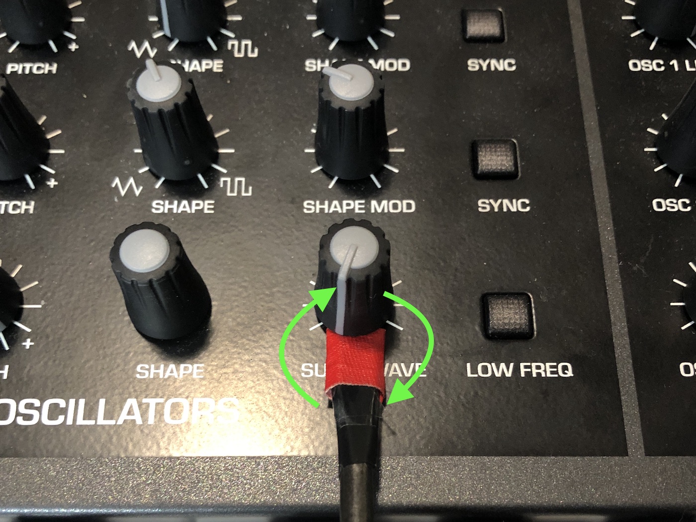
4. If it is difficult to remove the knobs, a flathead screwdriver wrapped with a thin layer of duct tape or masking tape can be used to assist you. The tape will protect both the top panel and the knob from damage. Slide the screwdriver between the bottom center of the knob and the top panel. Turn the screwdriver a small amount. Only a slight twist is required. Once the knob has moved a short distance it is easily removed by hand. Repeat the process as necessary.
Knob Removal
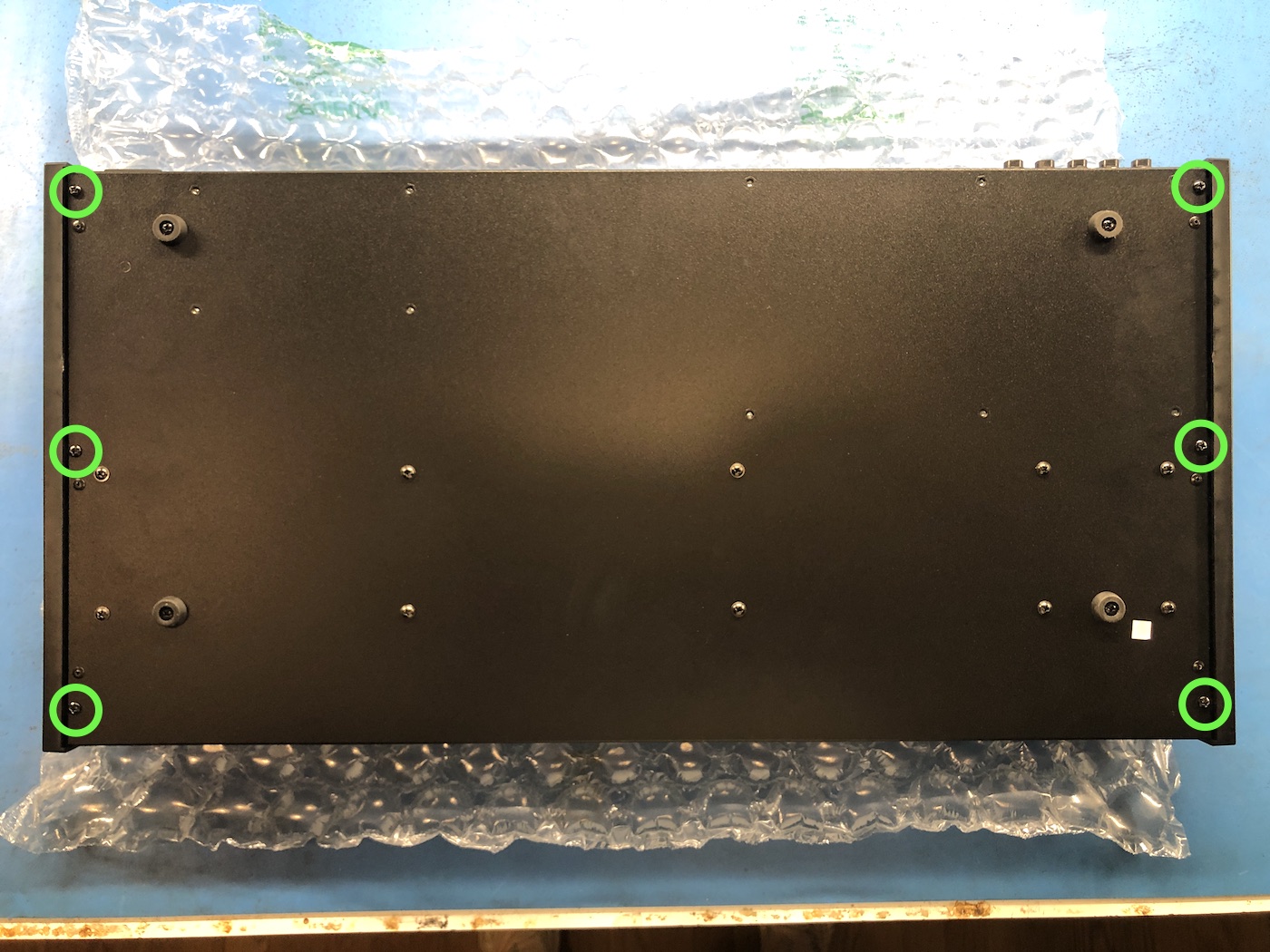
2. Flip the Take 5 upside down onto something soft, such as a strip of bubble wrap or a towel.
3. There are three screws on each side securing the plastic end caps to the bottom metalwork. Remove these screws and lift the sides up and out to free them.
Take 5 Bottom Screws
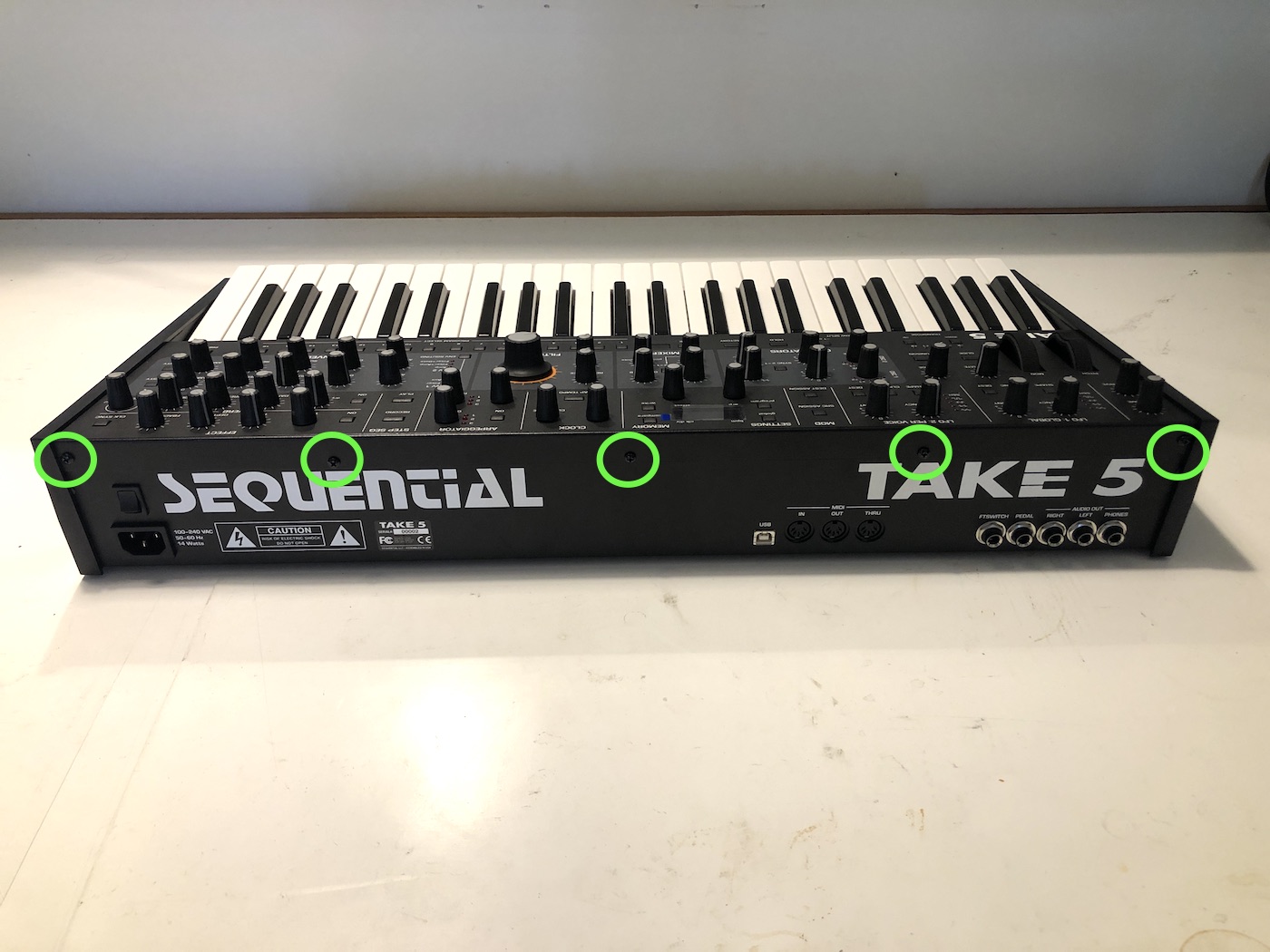
4. Flip the unit back over into its normal position.
5. Remove the 5 screws along the upper back of the synth.
Take 5 Rear Screws
6. Lift up the top metalwork and place it behind the bottom metalwork, on something soft such as a strip of bubble wrap or a towel. Be careful not to stress the single ribbon cable that connects the top and bottom of the synth.
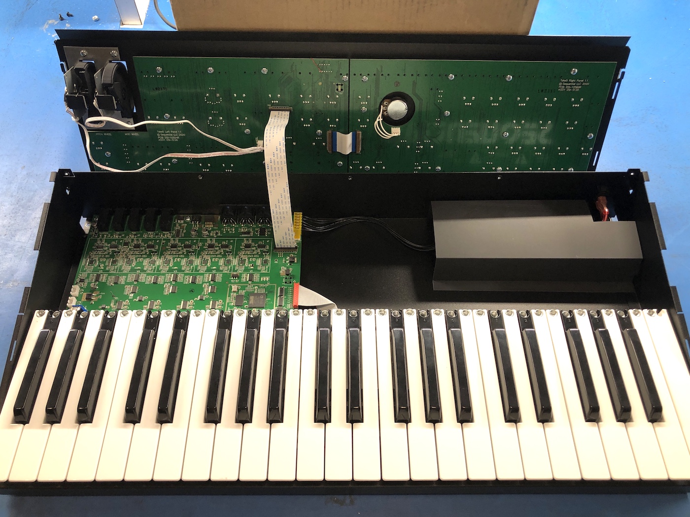
Take 5 Open
Removing the left panel board:
1. The left panel board has 4 connections to it. Please follow the directions below for removing these cables.
2. Start by locating the long ribbon cable that connects the main board to the left panel board. There is a thin, black locking tab on each connector that holds the ribbon cable in. The tab can be easily opened by gently lifting up on each end with your fingernails. The locking connectors don’t come out completely, they are fully unlocked after moving ~3 millimeters. On the left panel board side only, gently lift the locking connector out of place and remove the ribbon cable. When reinstalling the ribbon cable, make sure the tabs are open, slide the cable back into the slot, then close the tabs when the ribbon is fully inserted.
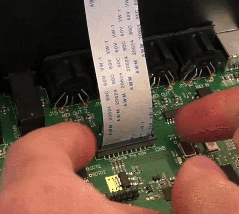
Take 5 FFC Ribbon Removal
3. Locate the small white ribbon cable that connects the two panel boards together. Using the same technique, gently unlock the black locking tab on the left panel board side only, then slide the cable out. When reinstalling the cable, make sure that the black tab is unlocked, then slide the ribbon cable into place and lock the connectors.
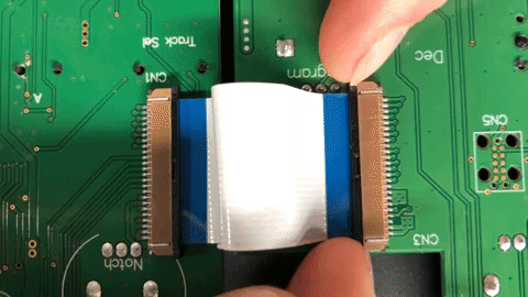
Take 5 Panel to Panel Connector
4. Disconnect the pitch and mod wheel connectors by pulling straight up on the white square plastic connector. DO NOT pull on the cables themselves.
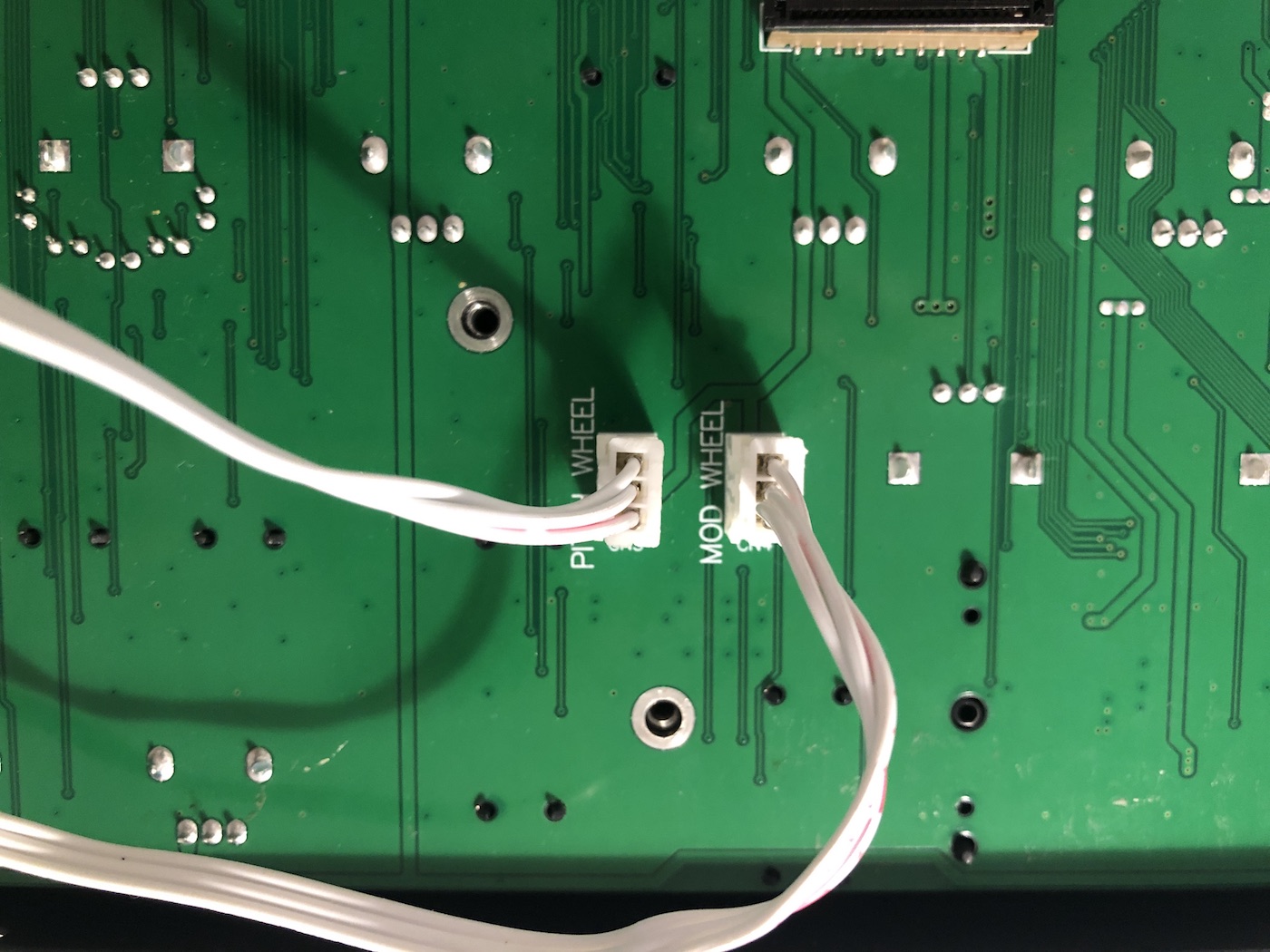
Take 5 Wheel Connectors
5. Remove the 10 silver screws securing the left panel to the metalwork.
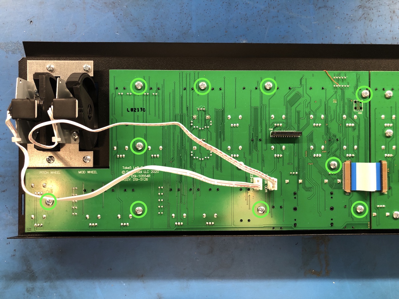
Take 5 Left Panel Screws
6. Install the replacement left panel PCB in reverse order, then move onto removing the right panel PCB using the instructions below.
Removing the right panel board:
1. The right panel board has 2 connections to it. Please follow the directions below for removing these cables.
2. Start by locating the short ribbon that connects the left and right panel boards together. There is a thin, black locking tab on each connector that holds the ribbon cable in. The tab can be easily opened by gently lifting up on each end with your fingernails. The locking connectors don’t come out completely, they are fully unlocked after moving ~3 millimeters. On the right panel board side only, gently lift the locking connector out of place and remove the ribbon cable. When reinstalling the ribbon cable, make sure the tabs are open, slide the cable back into the slot, then close the tabs when the ribbon is fully inserted.
Take 5 Panel to Panel Connector
3. Disconnect the white filter pot connector below the circle cutout. Gripping the connector directly, pull straight up with a slight wiggle to remove. DO NOT pull on the wires.
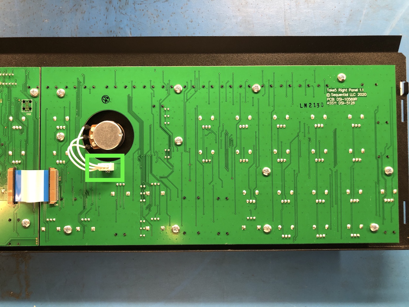
Take 5 Filter Connector
6. Remove the 12 silver screws holding the panel PCB in place and carefully free the right panel PCB from the metalwork.
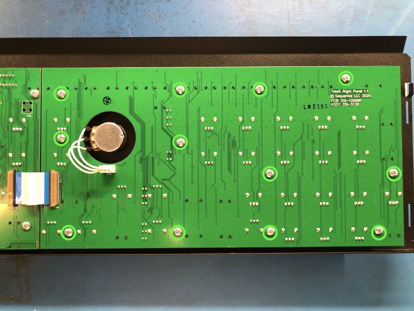
Take 5 Right Panel Screws
7. Install the replacement right panel PCB and reassemble the unit in reverse order.
Reinstalling the top panel and plastic sides:
1. There is a small metal tab on each side of the Take 5 that latches the top and bottom metal together.
2. Place the top metal panel onto the unit and line up the small tab with the cutout in the bottom metal. Slide the top panel down so the tab latches underneath the bottom metal.
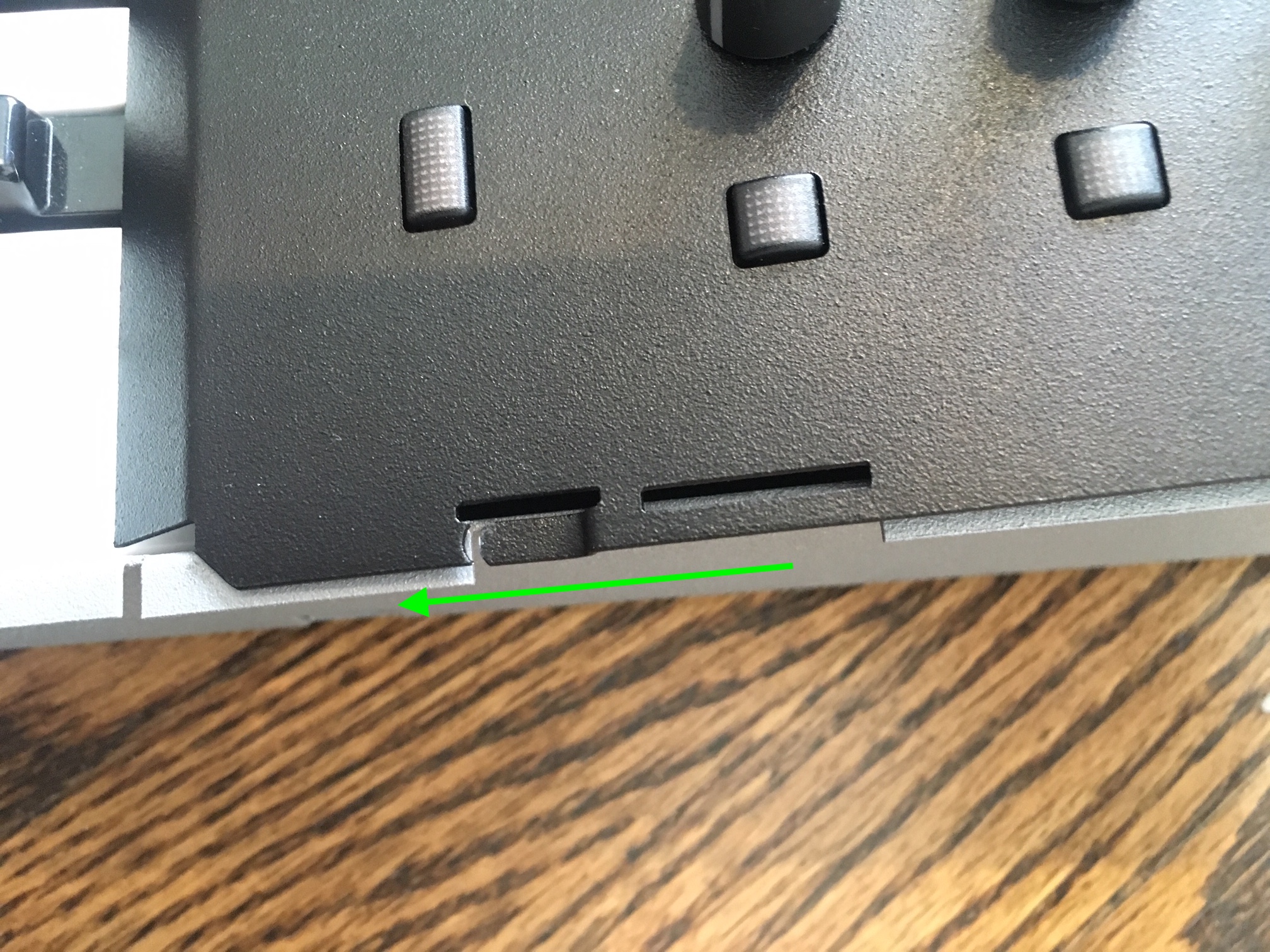
Take 5 Metal Tab
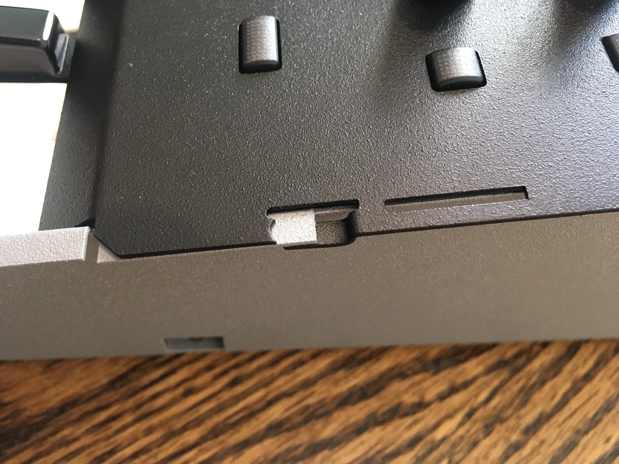
Take 5 Metal Tab
3. Each side panel has three lower screw slots and four upper plastic tabs.
4. Hook the upper plastic tabs into place at an angle, then push the lower screw slots into place. The side panels will click into place with a light amount of pressure.
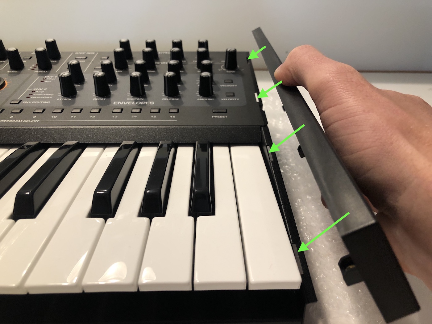
Take 5 Side Panels 1
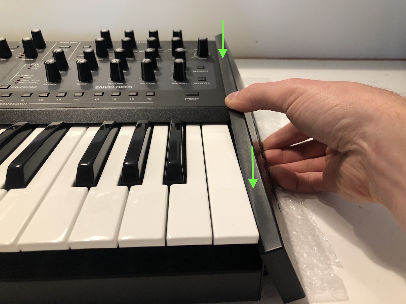
Take 5 Side Panels 2
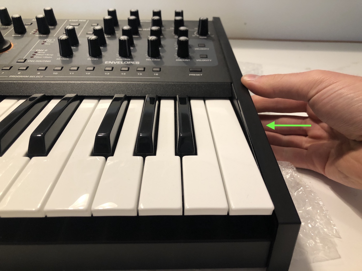
Take 5 Side Panels 3
5. While holding the side panels, flip the unit over onto something soft, like a strip of bubblewrap or a towel. Reinsert the three screws on each side to secure the plastic panels.
Please contact Sequential Technical Support if you have any questions regarding this procedure.