PROPHET-5 & PROPHET-10 CAP MOD
Performing the capacitor mod in the Prophet-5 or Prophet-10 Keyboard is a relatively easy procedure if you have some surface soldering experience, requiring little more than a screwdriver and a soldering iron.
Tools needed: Phillips head screwdriver, electronics soldering iron with fine tip, solder, tweezers.
Optional: Solder wick or solder sucker.
Getting inside the Prophet- 5 & Prophet-10:
1. First, unplug all power/MIDI/USB/audio cables.
- Note: Wood is sturdy but delicate, and can be scratched or damaged if you’re not careful. Take your time to ensure your wood remains in pristine condition during disassembly and reassembly.
2. Now unscrew the 6 screws on each of the wooden sides.
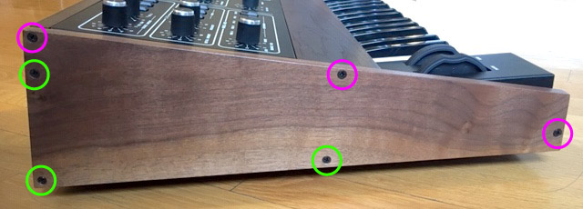
Left Wooden Side
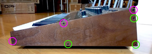
Right Wooden Side
- Note: There are two different types of screw, take care to keep them organized.
3. Underneath the left wooden side, unscrew the upper 3 screws from the metal.
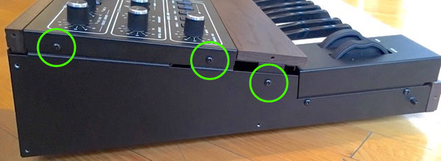
Left Side Screws
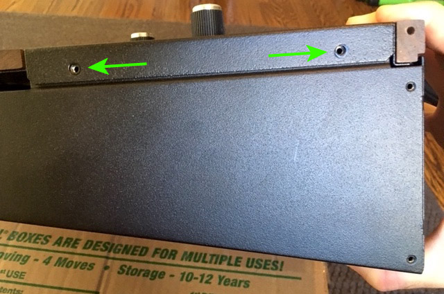
4. Underneath the right wooden side, unscrew the upper 3 screws from the metal.
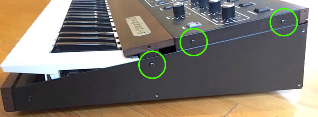
Right Side Screws
You can now lift the lid open from the front. It is hinged and it will stay open with the attached lanyard.
Removing the voice expansion (Prophet-10 only):
1. The voice expansion board sits on top of the main board in the tray above the keybed. Remove the 3 screws securing the voice expansion to the main board.
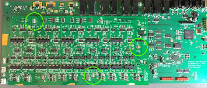
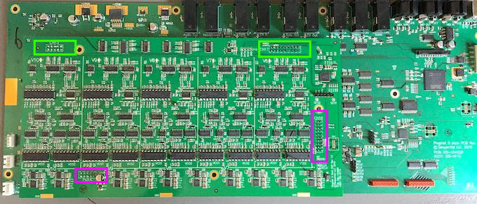
2. The voice expansion board has 4 connectors on the underside, sitting in sockets on the main board. The connector locations are easy to identify by finding the pairs of parallel soldered pins near the top, right, and bottom edges of the board. To remove the voice expansion, start at the back edge near the audio jacks and place your index fingers under the voice board near the connector locations. Applying medium force, alternate between each connector to slowly pry the 2 rear connectors free.
- Note: To avoid damage, take care to stop pulling as soon as the connectors are free as the 2 front connectors will still be attached.
P10 Voice Expansion
3. Move to the front connector locations and repeat the process. The front right connector will be fairly easy to remove. Use the same technique of alternating sides while pulling up slowly to wiggle the front left connector free. The voice expansion can now be lifted out and set aside.
Performing the capacitor mod:
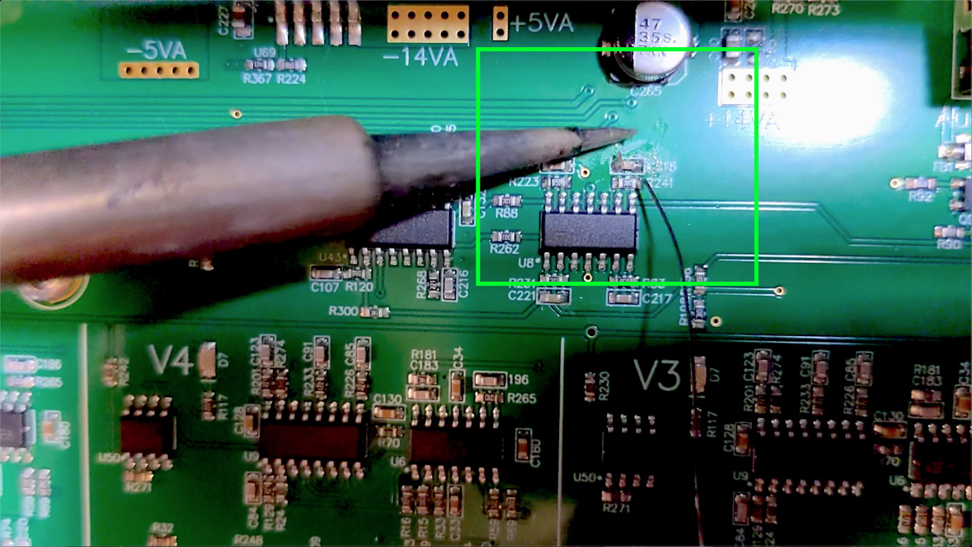
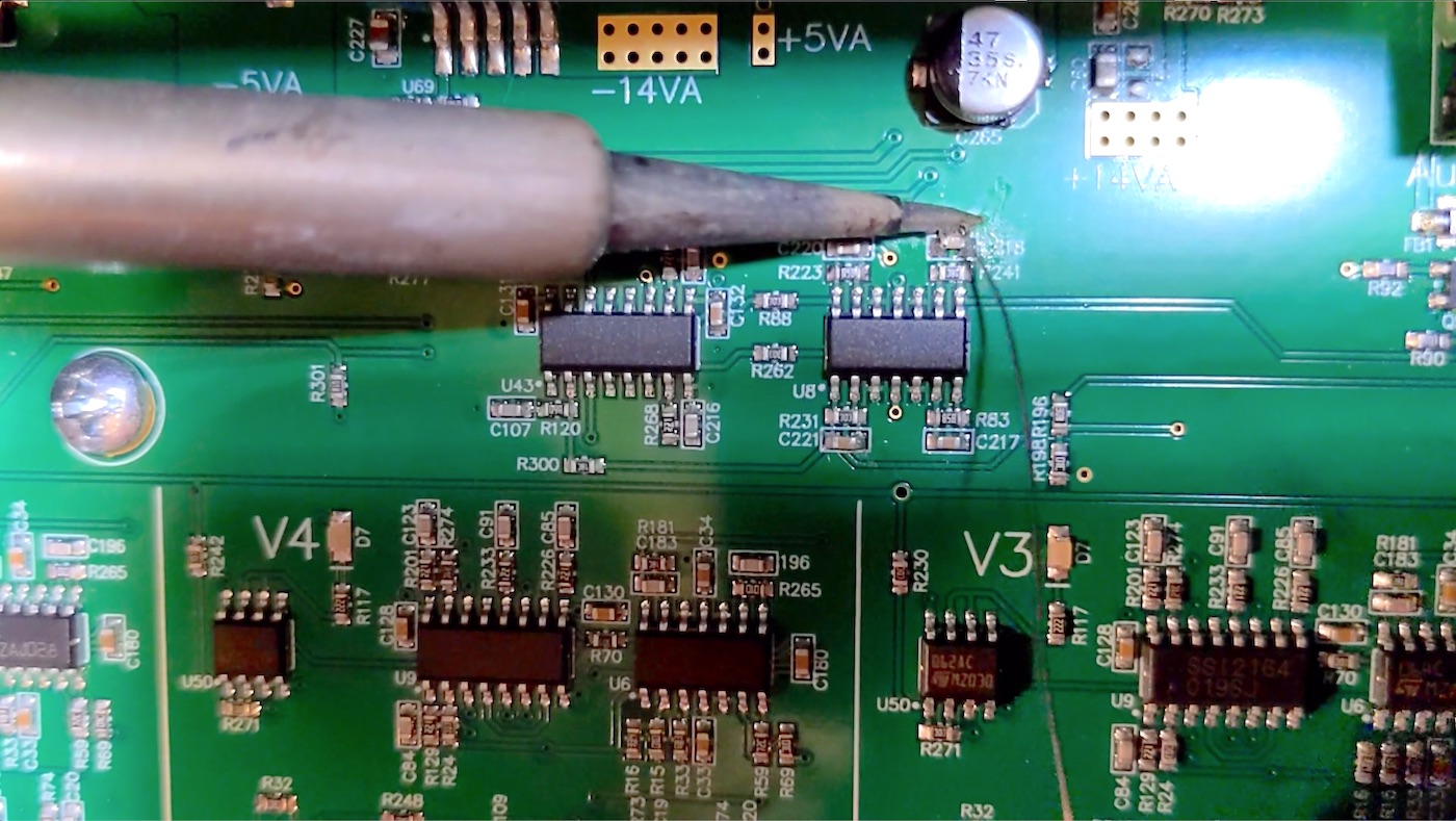
1. Locate the mod site on the mainboard, to the left and just below the audio jacks.
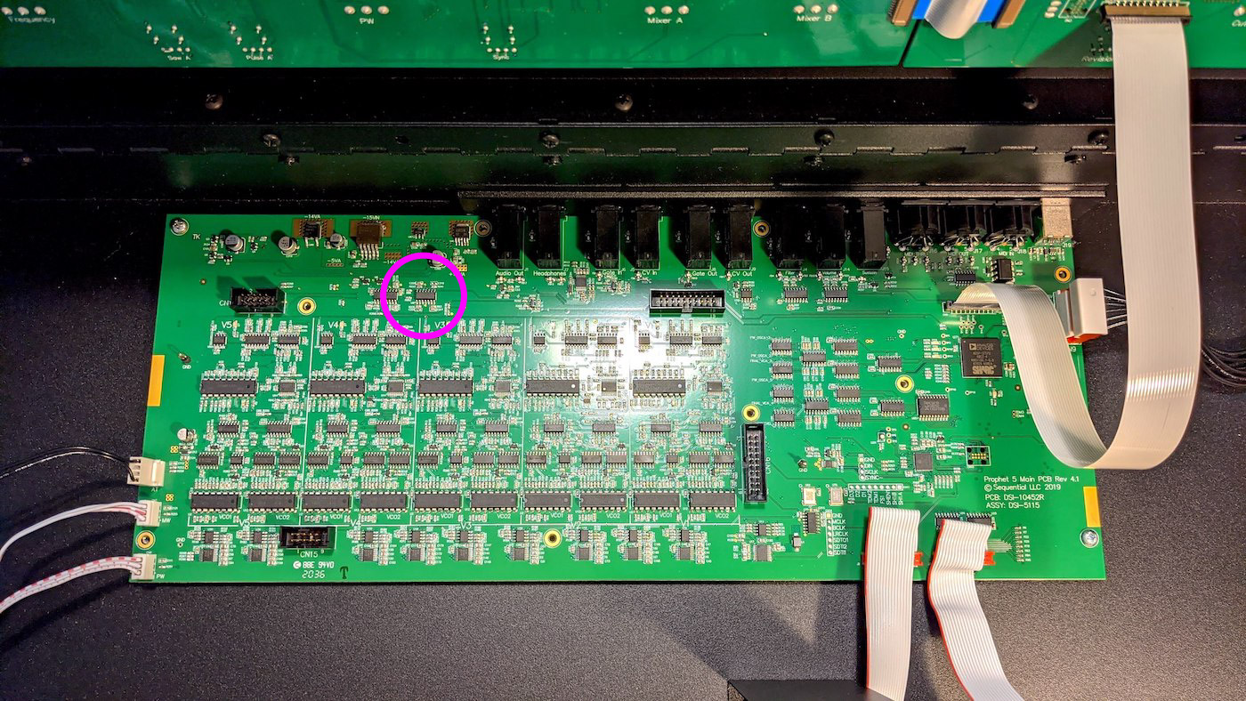
Mainboard Mod Location
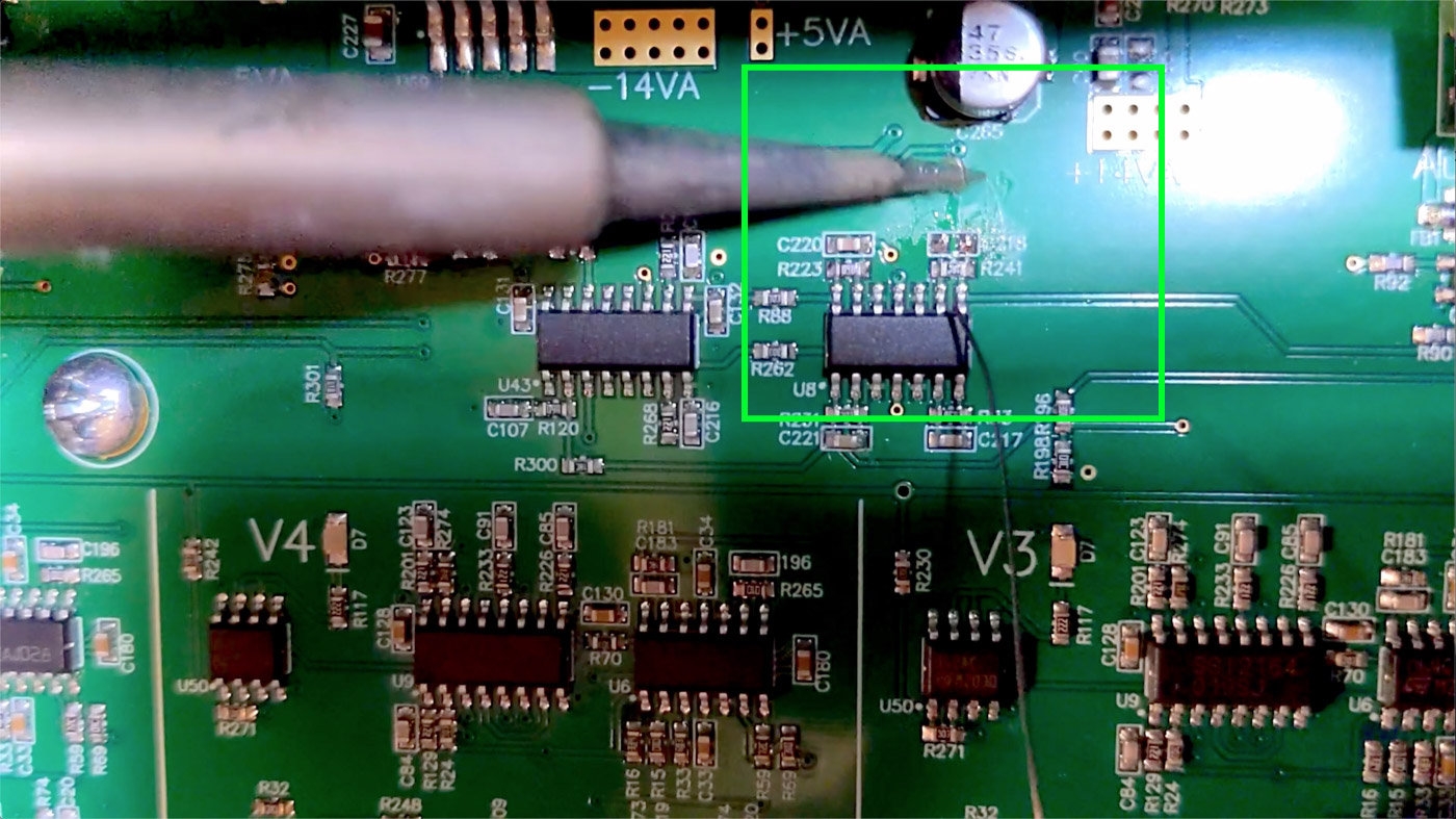
2. The capacitors to remove are in locations C218 and C221:
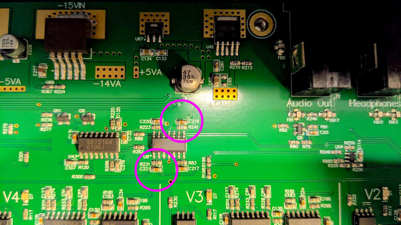
C218 and C221
Using your soldering iron, start by applying a decent amount of extra solder to each side of C218. You want to get a small glob of solder built up on both sides.
Solder Blob
3. Once you’ve built up solder blobs on both pads, put your soldering iron tip parallel to the capacitor so the barrel touches both sides simultaneously. This transfers maximum heat to the pads and the capacitor should become “loose” in just a few seconds.
Soldering Iron Parallel
4. Once the capacitor no longer feels attached, you can either use the soldering iron to scrape the capacitor off the pads, or use your tweezers to assist in lifting the capacitor away. Keep the soldering iron in contact with the capacitor while using the tweezers. Move the iron and tweezers away from the pad simultaneously.
Cap Removed
5. If you want to cleanup the mod site, you can use your soldering iron along with solder braid/wick or a solder sucker to remove excess solder. This step is optional, and as long as there isn’t a solder bridge between the pads any remaining solder will not affect operation.
- Note: If you are experienced with SMD techniques, a hot air rework station is an effective alternative method of removing the capacitors.
6. Repeat the capacitor removal process on site C221.
For reference, here’s a short video of the cap removal mod:
Reassemble the Prophet-5 or Prophet-10 in the reverse order:
1. If you have a Prophet-10, take care to align the pins on the connectors between the voice expansion and the mainboard. Press the voice expansion into place with medium force and once it’s fully seated, reinstall the 3 screws to secure it.
2. The top panel tends to lie a little too far forward when at rest. While the screws will still go in, the wood may be slightly out of alignment without some attention to detail.
Lid Resting
3. Take care to center align the top panel screw holes with the threads in the bottom panel. For the rear screw, this often means pushing down on the top panel or squeezing the top and bottom panel together with one hand while inserting and tightening the screw with the other. As long as it’s aligned front-to-back, the other two holes should also be aligned.
Lid Adjusted
- Note: Also pay attention to the vertical orientation of the hole and keep it centered on the threads, if pushed too far down the wood may not align properly.
4. When reinstalling the wood sides, put the top rear screw in first and align that corner with the wood trim.
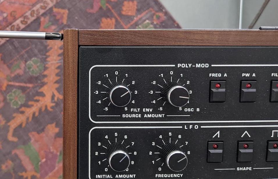
Corner Screw
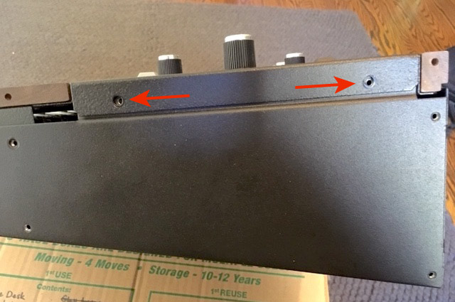
5. If, in step 2, you pushed/squeezed the top panel down too far, the second screw down in the rear doesn’t align with the threads in the metal. One way to check that is by looking at the gap in the back between the hinge and the ends. It should be the same width (top to bottom) all the way across.
Wood Side Alignment
- Note: Typically, it’s wider at the ends of the instrument, so when you push/squeeze it together it evens out. But it is possible to squeeze it too much which results in the gap being narrower at the ends.
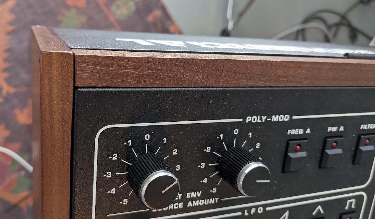
6. After that, any order for the remaining screws will work. Position the front edge of the side panel as flush to the font wood trim as you can.
Recalibrating the oscillators and filters:
1. After performing the cap mod, the Prophet-5 and Prophet-10 need to be recalibrated. Plug in the power cable and turn the unit on.
2. Press and hold the Record switch, and while holding press Tune. This resets the calibration table. Recalibrate the unit by pressing the Tune button.
- Note: The calibration table will need to be repopulated at various temperatures before the instrument feels like it’s not “going out of tune”. We recommend tuning immediately after power up when it’s cold, again as it warms up, and again when it’s been on for several hours in your normal working environment. In short, press Tune anytime the instrument sounds out of tune or when you bring it to a new location, and before long you’ll rarely have to tune it again.
Please contact Sequential Technical Support if you have any questions regarding the above procedure.